

Unplanned downtime on a viscous oil line doesn’t just cost you the price of a replacement part; it costs you production hours, compromised batch quality, and wasted labor. When handling heavy fluids like furnace oil, vegetable oil, or heavy base oils, a reactive maintenance strategy is a fast track to mechanical failure. This Oil Flow Meter maintenance guide strips away the theory and provides a blunt, practical framework for keeping your volumetric measurement accurate and your lines running.
Whether you are managing a chemical plant in Europe, an oil & gas facility in the Middle East, or overseeing Oil Flow Meter maintenance in India for Indian industrial plants, the physics of positive displacement measurement remain the same. Contaminated oil destroys gears, degraded seals cause leaks, and ignored strainers choke pump systems. Implementing a rigid preventive maintenance schedule for oil flow meter on viscous oil lines is the only way to guarantee the +/- 0.5% accuracy you paid for.
QUICK REFERENCE: MONTHLY PM CHECKLIST
- [ ] Verify display output matches control room SCADA (RS485/4-20mA).
- [ ] Inspect flange connections for micro-leaks.
- [ ] Check integrated mesh strainer differential pressure.
- [ ] Confirm flow rates remain within the 1.0 LPH to 24000 LPH operational band.
- [ ] Validate operating temperature is within the 150 C limit.
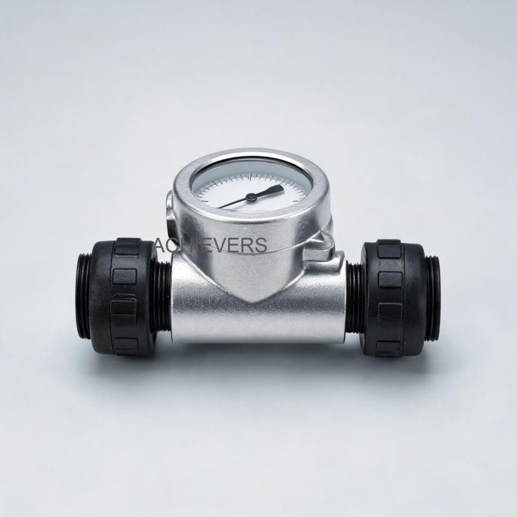
1. Product Overview and Critical Wear Components
Our Oil Flow Meter utilizes a robust oval gear positive displacement design. As viscous fluid passes through the chamber, it forces the gears to rotate, with each rotation representing a precise volume of liquid. Because this relies on extremely tight internal clearances, the mechanical integrity of the gears, shafts, and bearings is paramount.
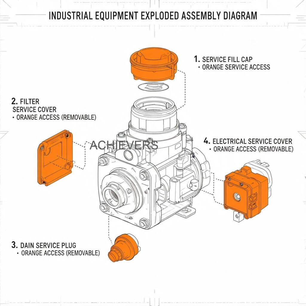
Critical wear components include:
- Integrated Mesh Strainer: The first line of defense against particulate matter. If this fails, the meter fails.
- Oval Gears and Shafts: Subject to mechanical wear if lubrication fails or abrasives enter the chamber.
- O-Rings and Chamber Seals: Degrade over time due to thermal cycling (especially on 150 C furnace oil lines) and chemical attack.
- Electronic Register: The digital display and transmission board (4-20 mA / RS485) are sensitive to moisture ingress and vibration.
Core Specifications to Monitor
| Specification | Parameter | Maintenance Implication |
| — | — | — |
| Line Size | 6mm to 150mm (1/4" to 6") | Larger lines require higher torque specs for flange bolts. |
| Flow Range | 1.0 LPH to 24000 LPH | Operating below minimum causes slip; exceeding maximum causes gear cavitation. |
| Accuracy | +/- 0.5% of reading | Deviation indicates gear wear or fluid bypass. |
| Repeatability | +/- 0.1% (up to 0.02%) | Poor repeatability usually points to electronic signal interference. |
| Max Temperature | 150 C | Prolonged operation at max temp accelerates seal degradation. |
| Output | 4-20 mA & RS485 MODBUS | Requires clean terminal contacts; inspect for corrosion. |
2. Preventive Maintenance Schedule
Standardize this schedule across your facilities. For lighter, less viscous applications, you might deploy a Fuel Flow Meter, but for heavy lube and furnace oils, stick to these rigorous intervals.
| Task | Frequency | Responsible | Est. Time | Notes |
| — | — | — | — | — |
| Visual leak & casing inspection | Daily | Line Operator | 5 mins | Check flanges, register base, and strainer cap. |
| Operating temperature check | Daily | Line Operator | 2 mins | Ensure fluid remains under 150 C max limit. |
| Mesh strainer blowdown/cleaning | Weekly | Maintenance Tech | 15 mins | Increase frequency for highly contaminated furnace oils. |
| Electronic signal verification | Monthly | Instrumentation | 10 mins | Verify 4-20mA and RS485 outputs match mechanical register. |
| Fastener torque check | Quarterly | Maintenance Tech | 20 mins | Vibration can loosen casing and flange bolts over time. |
| Seal inspection & replacement | Bi-Annually | Maintenance Tech | 45 mins | Replace O-rings if thermal hardening is detected. |
| Internal gear clearance check | Annually | Plant Engineer | 60 mins | Requires line shutdown and meter isolation. |
| Industrial oil flow meter accuracy verification procedure | Annually | Calibration Tech | 90 mins | Use a master meter or gravimetric proving method. |
| Register terminal cleaning | Annually | Instrumentation | 15 mins | Clean contacts with electrical contact cleaner; check for oxidation. |
| Complete factory overhaul | 3-5 Years | OEM/Supplier | N/A | Based on total volumetric throughput and fluid abrasiveness. |
3. Step-by-Step Procedures for Key Tasks
Procedure 1: Integrated Mesh Strainer Cleaning
A clogged strainer restricts flow, increases line pressure, and can lead to gear starvation or cavitation.
- Isolate the Meter: Close the upstream and downstream block valves to isolate the meter from the active oil line.
- Relieve Pressure: Safely bleed off internal line pressure using the designated bleed valve. Never open a pressurized meter.
- Remove Strainer Cap: Unbolt the strainer housing cap. For heavy furnace oils, residual fluid will be highly viscous and potentially hot. Wear appropriate PPE.
- Extract the Mesh: Carefully pull the integrated mesh strainer cylinder from the housing.
- Inspect for Damage: Check the mesh for tears, warping, or collapsed sections. A compromised strainer must be discarded.
- Clean the Mesh: Use a compatible solvent and a soft bristle brush to remove particulates. Do not use wire brushes that could deform the micron rating.
- Flush the Housing: Wipe the internal strainer housing clean of any settled sludge or metal shavings.
- Reassemble: Lubricate the cap O-ring with a compatible grease, seat the strainer, and tighten the cap to the specified torque. Slowly open the upstream valve to prime the system.
Procedure 2: Seal Replacement and Accuracy Verification
Monitoring the Oil Flow Meter spare parts and seal replacement interval is critical for preventing bypass leaks that destroy accuracy.
- Drain and Isolate: Isolate the meter, relieve pressure, and drain residual oil from the measuring chamber.
- Remove the Register: Unbolt and carefully lift the top electronic register. Disconnect data cables (4-20mA/RS485) cautiously.
- Unbolt the Measuring Chamber: Remove the faceplate bolts holding the gear chamber closed.
- Extract Old Seals: Carefully pry out the old O-rings and gaskets using a non-marring brass or plastic pick.
- Inspect Gears: While the chamber is open, manually rotate the oval gears. They should turn smoothly without grinding or catching.
- Install New Seals: Clean the gland grooves thoroughly. Seat the new OEM seals evenly without twisting them.
- Reassemble and Torque: Replace the faceplate and torque the bolts in a star pattern to ensure even pressure and prevent warping the aluminum alloy casing.
- Verify Accuracy: Run a known volume of fluid through the meter at normal operating temperature (e.g., 500 liters into a calibrated proving tank). Compare the meter's digital display against the tank volume to ensure it falls within the +/- 0.5% tolerance.
RED FLAG WARNING:
Never use compressed air to spin the oval gears during maintenance or cleaning. The lack of liquid lubrication combined with high-speed rotation will cause immediate and irreversible galling to the gear shafts and bearings.
4. On-Site Spare Parts to Stock
Relying on reactive shipping for replacement parts guarantees prolonged downtime. Every plant should establish an Oil Flow Meter supplier for manufacturers maintenance checklist and keep these items in local inventory.
| Part | Type | Recommended Qty | When to Replace |
| — | — | — | — |
| Integrated Mesh Strainer | Consumable | 2 per meter | If mesh is torn, warped, or cannot be fully cleaned. |
| O-Ring Kit (Viton/PTFE) | Wear Part | 2 sets per meter | Bi-annually, or if leaks or thermal hardening occur. |
| Oval Gear Set | Major Spare | 1 set per 5 meters | If physical scoring, wear, or accuracy loss is observed. |
| Display Board/Register | Electronic | 1 per site | If screen fails or RS485/4-20mA signal drops out permanently. |
| Flange Gaskets | Consumable | 4 per meter | Anytime the meter is removed from the pipework. |
5. Diagnosing Maintenance-Related Failures
When equipment fails, it leaves a trail of evidence. Use this diagnostic matrix to trace operational issues back to missed preventive maintenance.
| Failure Symptom | Missed Maintenance Task | Corrective Action |
| — | — | — |
| Meter reads lower than actual flow | Worn oval gears or degraded internal seals causing fluid bypass. | Replace oval gears and internal O-rings; recalibrate. |
| Flow rate drops drastically | Ignored mesh strainer cleaning interval. | Isolate meter, remove and clean/replace strainer mesh. |
| Meter stopped, fluid still flowing | Sheared gear shaft or broken coupling due to debris jamming gears. | Complete teardown; replace gears, shafts, and clean line. |
| Erratic electronic output to SCADA | Failure to inspect and clean RS485/4-20mA terminal connections. | Clean terminals with contact cleaner; check cable shielding. |
| Leaks around the faceplate | Exceeded seal replacement interval; thermal degradation. | De-pressurize line, replace main chamber seals, torque bolts. |
| Display is blank but signal works | Moisture ingress into the top register due to a failed cover seal. | Replace register unit and install new protective cover seal. |
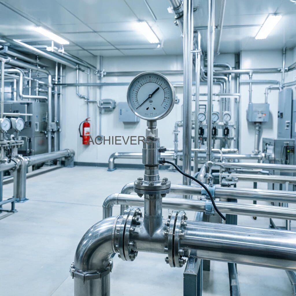
6. Extending Service Life in Global and High-Stress Conditions
Industrial environments vary wildly, from freezing offshore rigs to sweltering desert refineries. To get the maximum operational life out of your meter's lightweight aluminum alloy construction, adapt your maintenance to the environment:
- High Ambient Temperatures: If measuring 150 C furnace oil in a facility with high ambient heat, the electronic display can overheat. Ensure the register top is shaded from direct sunlight, and inspect the internal electronics for heat-stress discoloration annually.
- High Viscosity Start-Ups: Cold oil is exceptionally thick. Pushing cold, viscous base oils through the meter at maximum pump pressure can blow the internal seals. Always utilize a soft-start pump sequence or wait for heat tracing to bring the oil to operational temperature before flowing.
- Power Surges: The 4-20mA and RS485 Modbus circuits are robust but can be fried by heavy plant equipment cycling on and off. Ensure the meter is grounded properly and utilizing shielded cables to prevent signal drift and board burnout.
- Corrosive Environments: If installed in a coastal facility or near corrosive chemical processing lines, coat the exterior flange bolts with an anti-seize compound to ensure you can actually unbolt the meter when maintenance is due.
FAQ
Q: How often do I really need to clean the integrated mesh strainer?
A: For clean lube oils, monthly is usually sufficient. However, for heavy furnace oil or recycled fluids, you must check it weekly during the first month of installation. Establish your long-term frequency based on the debris accumulation found during these initial checks.
Q: The digital display is working, but my SCADA system is reading zero flow. What is wrong?
A: This is almost always an electrical issue, not mechanical. Check the 4-20mA or RS485 terminal blocks inside the register for loose wires, corrosion, or ground loop interference. If the display is counting, the gears are turning.
Q: Can I use this meter for water or highly corrosive chemicals?
A: No. The aluminum alloy construction and oval gear tolerances are designed specifically for the lubricating properties of oils (mineral, vegetable, lube, furnace). Pumping water or harsh chemicals will cause rapid mechanical wear and corrosion.
Q: Why is my meter suddenly reading 2-3% lower than my tank inventory?
A: A sudden drop in accuracy on a viscous line usually means fluid is bypassing the gears. This is caused by excessive gear wear, degraded internal chamber seals, or operating the system at a flow rate significantly below the 1.0 LPH minimum rating.
Q: Does viscosity affect the meter's calibration?
A: Positive displacement meters actually perform better with higher viscosity fluids because the thicker oil seals the micro-gaps between the gears and the chamber wall, reducing "slip." If you calibrate the meter on thin diesel and then switch to heavy furnace oil, you may see a slight shift in accuracy. Always verify accuracy with the actual process fluid.
Q: What is the maximum pressure drop I should expect?
A: The oval gear design features a naturally low pressure drop, making it suitable for gravity feed or in-line pump applications. However, pressure drop will increase as fluid viscosity increases or as the strainer becomes clogged. Monitor differential pressure across the meter to track strainer health.
To discuss your specific fluid handling needs, upgrade your site instrumentation, or request a detailed quote, contact our engineering team today. Please provide your exact product requirements, expected flow capacity, fluid viscosity, and site operating conditions so we can specify the ideal volumetric solution for your facility.