
Equipment downtime in heavy industries—whether in offshore oil and gas, remote mining operations, or high-throughput chemical plants—costs thousands of dollars per hour. When your fuel handling system halts due to air locks, erratic pulsing, or complete no-flow conditions, you need immediate field isolation and diagnosis, not a parts-replacement guessing game.
Swapping out components without identifying root causes like suction-side air ingress or blocked strainers guarantees the failure will repeat. This industrial diesel flow meter for manufacturers maintenance guide provides a direct, technical approach to diagnosing and resolving flow issues at the site level. Before you tear down the line or call service, work through this field-first troubleshooting process.
Quick Reference: Initial Field Diagnostic Checklist
- Verify upstream tank level and physical pump operation.
- Check isolation valves (both suction and discharge) to ensure they are fully open.
- Inspect the upstream Y-strainer or basket filter for debris/clogging.
- Bleed the line of air using the highest point bleed valve.
- Confirm operating pressure is within the rated 3.5 bar limit.
- Validate that fluid viscosity matches the meter’s 8–5000 mPas specification.
1. How the डीजल फ्लो मीटर Works Under Industrial Conditions
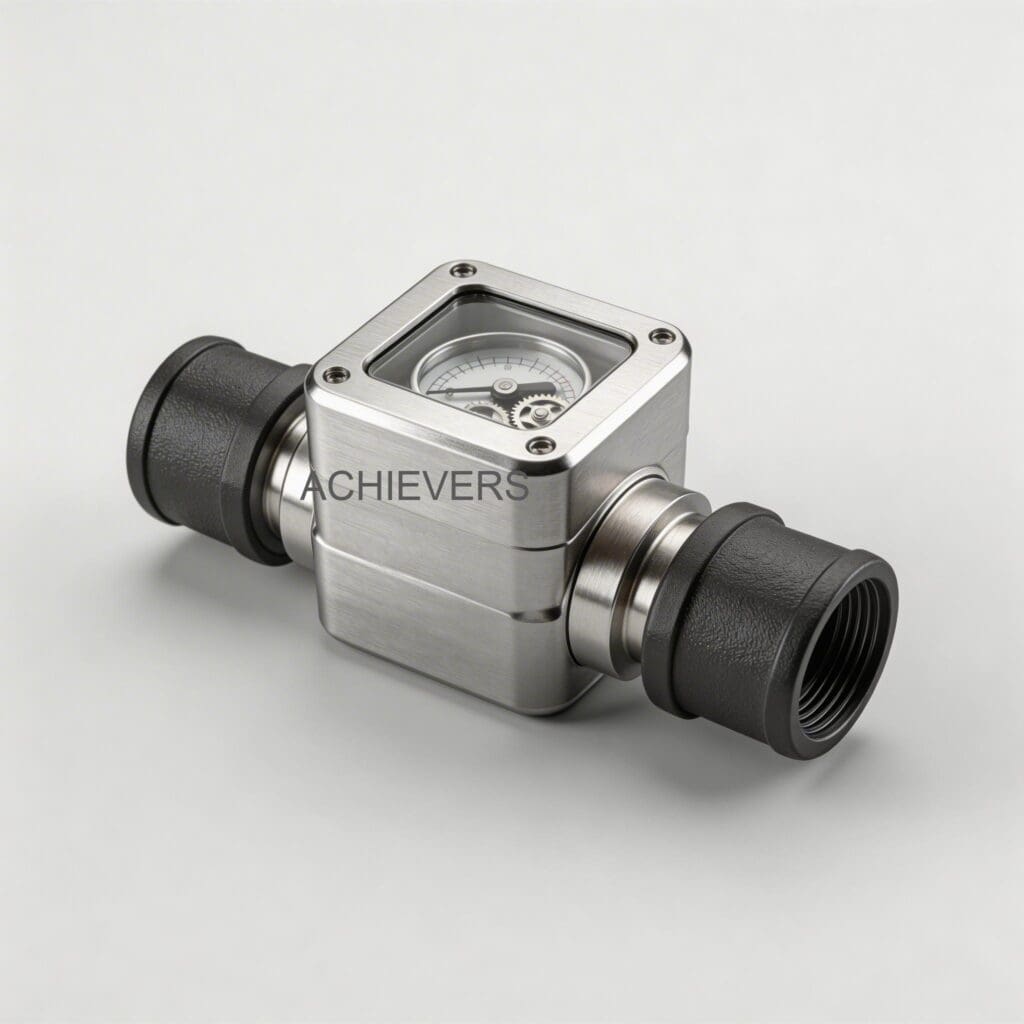
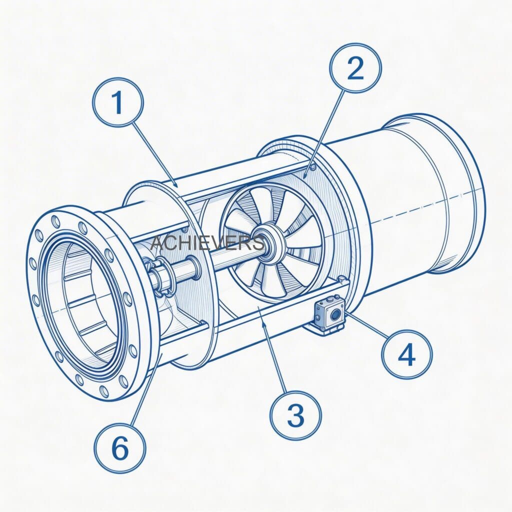
Understanding the operational baseline is critical for troubleshooting. The डीजल फ्लो मीटर operates on a positive displacement principle. It utilizes precision-machined rotors to measure discrete volumes of fluid with every rotation. Because it separates fluid into exact volumetric compartments, it is highly accurate (+/- 0.5%) but strictly relies on a solid column of liquid.
Air ingress or vapor bubbles (cavitation) displace liquid volume, leading to over-registration or "air locks" where the rotors spin freely or lock against air pressure. The meter is independent of viscosity fluctuations within its specified range, but extreme temperature drops can cause paraffin wax dropout in diesel, fouling the measurement chamber.
Technical Specifications Baseline
| विनिर्देश | पैरामीटर मान | Impact on Troubleshooting |
| — | — | — |
| शुद्धता | +/- 0.5% | Drift beyond this indicates wear, debris, or air ingress. |
| Line Sizes | 1/2 inch to 4 inch | Dictates required straight-pipe run and flange torque specs. |
| Viscosity Range | 8 to 5000 mPas | Outside this range causes pressure drops or internal slip. |
| Max Operating Pressure | 50 psi / 3.5 bar | Exceeding this damages O-rings and causes external leaks. |
| Display | 9×4 digit electronic counter | Blank display points to electrical, not mechanical, faults. |

2. Troubleshooting Matrix: Common Faults and Fixes
Use this matrix to isolate symptoms before taking the meter offline.
| लक्षण | संभावित कारण | निदान के चरण | हल करना |
| — | — | — | — |
| Zero Flow Indication (Pump running) | Air lock or closed downstream valve | Check system pressure. Listen for pump deadheading. | Bleed line at highest point; open all valves. |
| Erratic / Pulsing Delivery | Cavitation or suction-side air leak | Inspect upstream pipe joints. Check pump NPSH. | Tighten suction flanges; replace pump seals. |
| Complete No-Flow (Line open) | Blocked rotor or seized chamber | Check upstream strainer. Isolate meter and rotate manually. | Clean strainer; flush chamber to remove debris. |
| Display Error / Blank | Power loss or dead battery | Check 9×4 electronic counter power feed. | Restore power; replace battery/display module. |
| External Leakage | Worn seals or over-pressurization | Check operating pressure against 3.5 bar limit. Inspect O-rings. | Reduce line pressure; replace flange gaskets. |
| Abnormal Grinding Noise | Bearing failure or metal in chamber | Listen closely to housing. Check downstream filter for metal. | Take offline immediately. Rebuild or replace rotors. |
| Accuracy Drift (Over-reading) | Air passing through meter | Run bucket test. Check for foaming in discharge. | Eliminate suction leaks; install air eliminator. |
| Accuracy Drift (Under-reading) | Internal wear / fluid slip | Check fluid viscosity. Inspect rotors for clearance wear. | Recalibrate if minor wear; replace rotors if severe. |
| Sensor / Output Loss | Fouled sensor or severed wire | Check pulse output with multimeter. Inspect for wax buildup. | Clean sensor face; repair damaged signal cables. |
| Valve Not Responding | Blocked pilot port or failed solenoid | Test solenoid continuity. Check pilot lines for debris. | Clean pilot ports; replace faulty solenoid coil. |
3. चरण-दर-चरण क्षेत्र निदान प्रक्रिया
When facing a no-flow or pulsing condition, follow this sequence to restore operations quickly while maintaining ISO safety standards.
- Isolate the Fluid Line: Shut down the transfer pump and close both upstream and downstream block valves. Lock out and tag out (LOTO) the system.
- Inspect the Upstream Strainer: Open the strainer housing. Remove and inspect the mesh. A clogged strainer creates a massive pressure drop, leading to cavitation and pulsing flow. Clean and reinstall.
- Verify Operating Pressure: Install a pressure gauge directly upstream of the डीजल फ्लो मीटर. Confirm the system is not exceeding 50 psi (3.5 bar). Over-pressurization causes bypass leakage and locks the rotors.
- Bleed the Air Lock: Open the highest bleed valve in the piping layout. If no bleed valve exists, carefully crack the upstream flange of the meter until clear diesel (no bubbles) weeps out, then re-torque to spec.
- Check for Suction-Side Air Leaks: If flow is pulsing, the pump is pulling air. Inspect all threaded connections, flanges, and pump shaft seals upstream of the meter.
- Manually Verify Rotor Movement: If flow remains blocked, remove the meter register/counter head. Use a non-sparking tool to gently turn the magnetic drive or rotor shaft. If it refuses to turn, debris has seized the chamber.
- Inspect the Electronic Counter Linkage: If the rotors turn smoothly but the 9×4 digit counter does not register, check the magnetic coupling or pulse transmitter for separation, wax fouling, or electrical failure.
- Perform a Volumetric Calibration Test: Once flow is restored, dispense a known volume (e.g., 100 liters) into a certified proving tank. Compare the mechanical/electronic read-out to the prover volume. Adjust calibration screws or digital K-factors if the accuracy falls outside the +/- 0.5% range.
Red Flag Warning: Cavitation vs. Air Ingress
Do not confuse air ingress (leaks pulling ambient air into the line) with cavitation (fluid vaporizing due to extreme pressure drops). Installing an air eliminator will fix air ingress but will not fix cavitation. If your strainer is blocked or your suction pipe is too narrow, the fluid is vaporizing. You must resolve the upstream restriction.
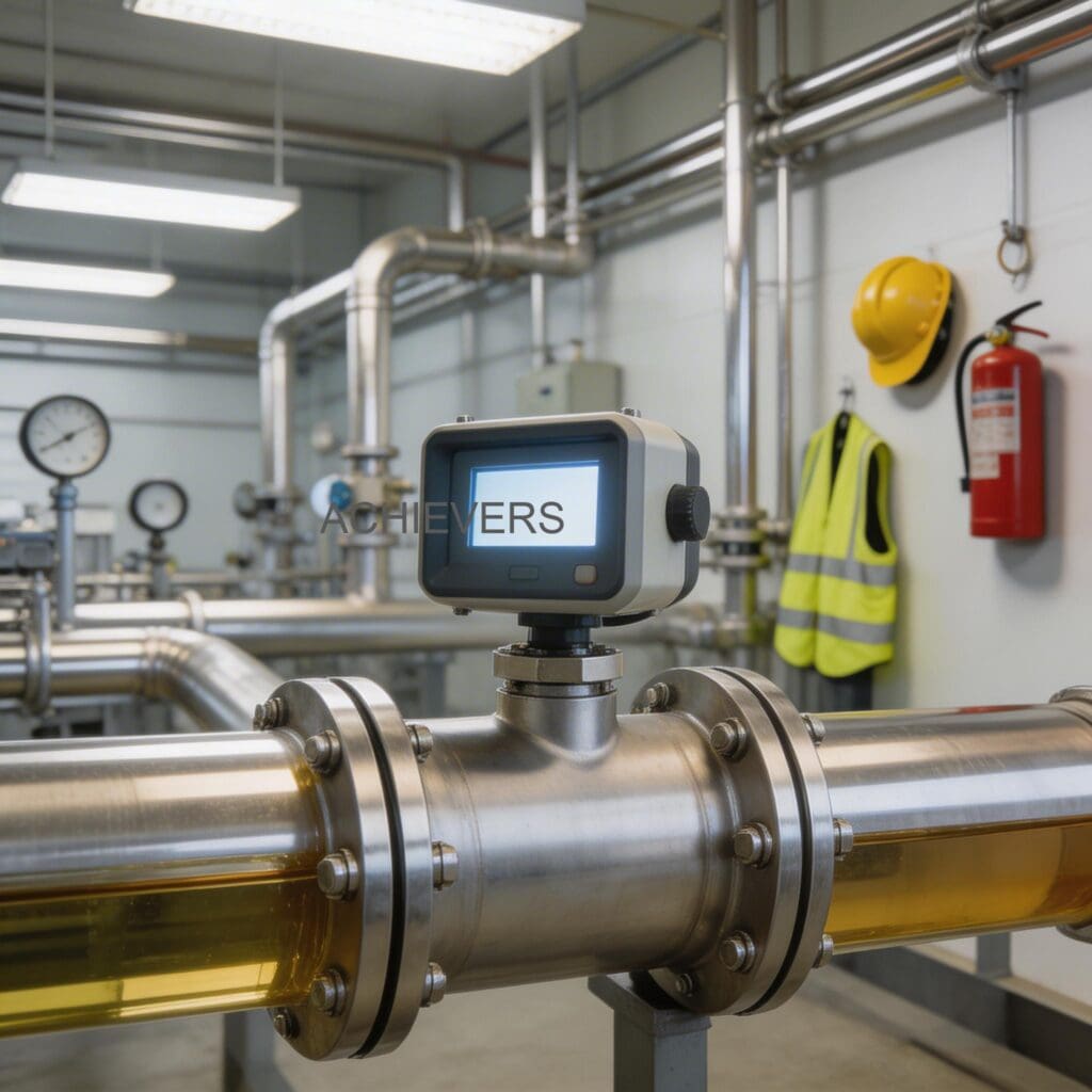
4. Installation and Setup Errors That Cause Ongoing Problems
A large percentage of Diesel Flow Meter troubleshooting calls stem from poor initial plant integration. If you are experiencing chronic issues, check your site layout against these parameters.
| Installation Error | Resulting Symptom | Required Correction |
| — | — | — |
| Meter installed at the highest piping point | Chronic air locks and over-registration | Relocate meter to a lower section of the line or install an upstream air eliminator. |
| No upstream strainer installed | Rotors seizing, internal scoring, total flow blockage | Install a mesh strainer (typically 100 micron for diesel) immediately upstream. |
| Placed too close to pump discharge | Erratic readings from extreme fluid turbulence | Ensure straight pipe runs (typically 10x diameter upstream, 5x downstream). |
| Rigid piping with high vibration | Flange leaks and electronic counter resets | Install flexible braided compensators to isolate vibration. |
| Incorrect flow direction | Meter blocks flow or registers in reverse | Remount meter observing the directional arrow cast into the housing. |
| Plumbed in parallel without check valves | Reverse flow and inaccurate totalization | Install non-return (check) valves downstream of each meter in the manifold. |
For facilities managing wider hydrocarbon distribution, standardizing your piping approach across your entire fleet, including your ईंधन डिस्पेंसर terminals and तेल प्रवाह मीटर lines, will drastically reduce maintenance overhead.
5. Preventive Maintenance to Avoid Recurrence
Preventive maintenance is cheaper than reactive downtime. Implement this schedule based on standard global operating conditions.
- साप्ताहिक: Bleed air from high points. Check the 9×4 digit electronic counter for clarity and battery health. Inspect flange joints for weeping.
- महीने के: Isolate and clean the upstream strainer. Perform a quick volumetric bucket test to ensure accuracy remains near the 0.5% baseline.
- त्रैमासिक: Inspect the integration between the diesel flow meter supplier technical support checklist and your site's SCADA system (if utilizing pulse outputs). Check ticket printer paper rolls and ribbon ink if equipped.
- वार्षिक: Drain the measurement chamber to inspect for paraffin wax buildup or sludge. Replace standard O-rings and gaskets to prevent sudden high-pressure blowouts.
6. When to Call Service vs. Fix Yourself
Knowing your maintenance limits ensures you don't void warranties or compromise ATEX/UL certifications.
Fix Yourself (Field Level):
- Clearing blocked strainers and filters.
- Bleeding air locks from the piping.
- Tightening flanges and replacing external O-rings.
- Resetting the electronic counter or replacing display batteries.
- Recalibrating the meter using the standard proving process.
Call Service (Factory Level):
- Rotors are physically jammed and will not turn after back-flushing.
- Internal measurement chamber shows deep gouging or scoring from metal debris.
- The meter consistently falls outside the 0.5% accuracy range despite field calibration.
- Replacement of internal bearings or timing gears.
अक्सर पूछे जाने वाले प्रश्न
Q: Can extreme cold weather cause my meter to stop flowing?
A: Yes. In extreme cold, diesel can reach its cloud point, causing paraffin wax to precipitate. This wax coats the internal rotors and housing, acting as a brake. Heat tracing or insulation is required in these environments.
Q: Why does my electronic counter display erratic numbers when the pump turns on?
A: This is usually caused by electromagnetic interference (EMI) from the pump motor or VFD cable. Ensure the meter's signal cables are shielded and routed away from high-voltage power lines. High physical vibration can also bounce the magnetic pickup.
Q: How often do I need to replace the ticket printer paper on my meter?
A: It depends on your batch frequency. However, always keep thermal printer mechanisms clean from industrial dust, and use the exact paper roll dimensions specified by the manufacturer to prevent feed jams.
Q: My flow meter is reading 5% higher than the tank inventory. What causes this?
A: The most common cause of over-registration is air passing through the meter. Because it measures volume, air bubbles are counted as liquid fuel. Inspect the suction side of your pump for air leaks and ensure your air eliminator is functioning.
Q: Is it safe to use this meter for higher viscosity oils if I change my fluids?
A: The meter is rated for a viscosity range of 8 to 5000 mPas. As long as the new oil falls within this range, the meter will function accurately, though you may need to adjust your pump pressure to account for higher resistance.
Q: What is the maximum pressure this meter can handle during a line surge?
A: The maximum operating pressure is 50 psi (3.5 bar). Sustained operations or surges above this will compromise the seals, leading to external leaks and potential internal fluid slip.
Q: Do I need a straight run of pipe before the meter?
A: Positive displacement meters are less sensitive to turbulence than turbine meters, but a standard straight run (e.g., 5 to 10 times the pipe diameter) is always recommended to ensure smooth fluid entry and reduce wear on the rotors.
Stop letting un-diagnosed flow interruptions dictate your production schedule. If your site is struggling with chronic fluid transfer issues, air lock complexities, or accuracy drift that field maintenance can't solve, contact our technical team to discuss your application. Specify your exact flow rate, fluid viscosity, and site conditions, and we will engineer a precise dispensing solution for your facility.