
Equipment downtime and fuel inventory discrepancies drain profitability at high-volume industrial sites. When a Diesel Dispenser starts delivering inaccurate meter readings or experiencing preset cut-off failures, fleet managers and site operators face immediate operational bottlenecks. Replacing parts blindly wastes time and maintenance budget; you need a systematic, engineering-led diagnostic approach to isolate the root cause.
Inaccurate dispensing typically stems from four primary culprits: suction-side air ingress, filter restriction, bypass/relief valve malfunctions, or calibration drift in the internal flow sensor. This guide provides a field-tested diagnostic path to troubleshoot these issues without guesswork. By following this protocol, maintenance teams can quickly restore dispensing precision, ensure compliance with international metrology standards, and eliminate the costly cycle of trial-and-error repairs.
QUICK REFERENCE: Dispenser Diagnostic Checklist
- Verify supply tank levels to rule out dry-running.
- Inspect the 25 mm inlet/outlet lines for blockages or collapsed hoses.
- Check the auto shut-off nozzle venturi port for debris causing premature cut-off.
- Confirm the oval gear flow meter registers flow smoothly without mechanical binding.
- Verify the internal bypass valve is fully seated and not relieving pressure prematurely.
- Ensure the 0.375 kW motor is receiving stable, correct voltage.
1. How the Equipment Works
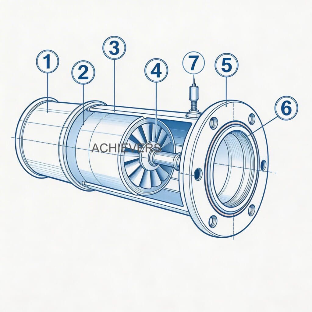
To troubleshoot effectively, you must understand the flow path and measurement principles of the Diesel Dispenser. The system utilizes a positive displacement (P.D.) pumping and metering mechanism, designed for rugged industrial use and high accuracy (+/-0.5%).
Fluid enters through a 25 mm inlet, typically drawn by a self-priming vane or gear pump powered by a 0.375 kW motor. The pump pressurizes the fluid to approximately 3 Bar. Before reaching the measurement chamber, the fuel passes through large-capacity reusable filters to prevent particulates from damaging precision components.
Measurement is handled by a high-accuracy P.D. flow sensor, specifically an oval gear flow meter. As fluid passes through this chamber, the pressure differential forces the oval gears to rotate. Because the volume of fluid displaced per rotation is fixed, counting the rotations provides highly accurate batch and cumulative totaliser readings (up to 9999 L per batch, and 9999999 L cumulative). Finally, the fluid exits through a 4 m rubber hose and an auto shut-off nozzle designed for safe tank topping.
The components most prone to failure due to harsh environments or poor fuel quality include the suction filter (clogging), the auto shut-off nozzle (vacuum tube blockage), and the bypass valve (sticking open due to debris).

2. Troubleshooting Matrix
Use this matrix to match your specific symptom to the likely cause and correct diagnostic path.
| Symptom | Likely Cause | Diagnosis Steps | Fix |
| — | — | — | — |
| Zero reading on display | Display/Totaliser power fault or broken sensor link. | Check electrical connections to the display. Inspect magnetic pickup/sensor at the oval gear. | Reconnect wiring. Replace magnetic sensor if no pulse is detected. |
| Erratic or jumping reading | Air ingress on the suction side. | Inspect suction line joints, check valves, and pump shaft seals for leaks. | Tighten fittings, apply thread sealant, replace worn shaft seals. |
| Consistent over-reading (dispenses less than shown) | Calibration drift or air in the line. | Use a certified volumetric proving can. Check for foam in the dispensed diesel. | Purge air from the system. Recalibrate the meter mechanically or electronically. |
| Consistent under-reading (dispenses more than shown) | Worn oval gears or fluid bypassing the meter. | Check for meter wear. Prove volume at high and low flow rates. | Replace oval gears or entire Diesel Flow Meter assembly if tolerances are lost. |
| Preset cut-off fails (overfills) | Sticking solenoid valve or nozzle failure. | Test preset batch electrically. Check if nozzle venturi is blocked. | Clean/rebuild solenoid valve. Clear nozzle venturi port. |
| Premature shut-off (clicks off constantly) | Auto shut-off nozzle vacuum tube blocked or flow rate too high. | Inspect the tip of the nozzle. Check tank venting. | Clean nozzle tip with compressed air. Ensure vehicle tank vent is clear. |
| Low flow rate (< 60 LPM) | Clogged reusable filter or sticking bypass valve. | Check pump discharge pressure. Inspect filter element. | Clean or replace the filter element. Clean and reseat bypass valve. |
| Excessive noise/cavitation | Starved suction or high fluid viscosity (cold temps). | Check for collapsed suction hose or undersized piping. | Replace collapsed hoses. Upsize suction line if run is too long. |
| Leakage from pump housing | Blown O-rings or worn mechanical seal. | Visually identify leak source while pump is running at 3 Bar. | Replace seals and O-rings using a designated rebuild kit. |
| Motor trips breaker | Mechanical binding or electrical short. | Spin pump shaft manually. Megger test the 0.375 kW motor. | Clear debris from pump/meter. Replace motor if windings are shorted. |
3. Step-by-Step Field Diagnosis Procedure
When facing accuracy or operational issues, avoid random adjustments. Follow this structured 8-step protocol.
Required Tools: Certified volumetric proving can (e.g., 20L or 50L), 0-5 Bar pressure gauge, multimeter, standard metric wrench set, and thread sealant.
- Verify Supply and Suction Integrity: Start at the source. Ensure the bulk tank has adequate fuel. Inspect the entire suction line from the tank to the dispenser inlet for wet spots (indicating leaks) or crimps. A compromised suction line introduces air, which the meter will read as fluid, destroying accuracy.
- Inspect the Filtration System: Isolate the dispenser and open the filter housing. Remove the large-capacity reusable filter. If it is heavily fouled with sludge or microbiological growth, clean or replace it. Restricted flow causes pump cavitation and erratic meter operation.
- Check Operating Pressure: Install a pressure gauge at the pump discharge port. Run the dispenser into a test container. The system should maintain a steady working pressure near 3 Bar. Fluctuating pressure indicates air ingress or a failing bypass valve.
- Test the Auto Shut-Off Nozzle: If the issue is premature cut-off, inspect the small venturi hole near the tip of the metal gun. Use a fine wire or compressed air to clear any dirt. Verify the diaphragm inside the nozzle moves freely.
- Evaluate the Bypass Valve: If flow is low but the filter is clean, the pump's internal bypass valve may be stuck partially open. Remove the valve cap, extract the spring and poppet, and inspect for scoring or debris. Clean and reinstall.
- Perform a Volumetric Proving Test: Dispense fuel into a certified, temperature-corrected proving can at the maximum flow rate. Record the meter reading versus the actual volume in the can. Repeat at a slow flow rate.
- Analyze the Proving Data: If the error is consistent across high and low flow rates, the system requires recalibration. If the meter is highly accurate at high flow but loses accuracy at low flow, the oval gears are worn and fuel is slipping past them.
- Adjust Calibration: Depending on the exact model (e.g., CE-130), locate the calibration adjustment mechanism. For mechanical totalisers, this involves adjusting a calibration screw that alters the bypass flow within the meter block. Make minor incremental adjustments and re-test until precision is within +/-0.5%.
RED FLAG WARNING: If the oval gear flow meter consistently over-registers (shows more fuel dispensed than is actually in your proving can), you almost certainly have an air ingress problem on the suction side, not a failed meter. Positive displacement meters will measure air just as accurately as fluid. Do not attempt to recalibrate the meter until the suction line is pressure-tested and completely sealed.
4. Installation and Setup Errors That Cause Ongoing Problems
Many troubleshooting calls originate from incorrect initial site setup rather than equipment failure. Ensure your Fuel Dispenser setup avoids these common engineering oversights.
| Installation Error | Resulting Symptom | Engineering Correction |
| — | — | — |
| Undersized suction piping | Pump cavitation, noisy operation, low flow rate. | Use piping at least equal to the 25 mm pump inlet; upsize for runs over 10 meters. |
| Missing anti-siphon valve | Fuel drains back to tank; dry running on startup. | Install a properly rated anti-siphon or foot valve at the tank suction point. |
| Excessive suction lift | Vapor lock, inability to prime, erratic meter readings. | Keep suction lift under 3 meters vertical. Push fluids with submersible pumps if lift is too high. |
| No thermal relief in piping | Blown seals, ruptured hoses during temperature spikes. | Install a thermal pressure relief valve in closed piping runs exposed to sunlight. |
| Improper electrical grounding | Display resetting randomly, static discharge risk. | Connect equipment to a certified earth ground according to ATEX/local hazardous area standards. |
| Rigid piping directly to unit | Vibration damage to dispenser frame and internal leaks. | Use a short flexible braided connector between rigid site piping and the dispenser inlet. |
5. Preventive Maintenance to Avoid Recurrence
Maintaining a precision instrument in a harsh industrial environment requires strict adherence to a maintenance schedule. Implementing these steps will maximize operational life and maintain the guaranteed +/-0.5% precision.
- Weekly: Inspect the 4 m rubber hose for abrasions, cracking, or exposed braiding. Check the auto shut-off nozzle for damage and clean the spout. Verify the totaliser zeroes out smoothly.
- Monthly: Open the strainer/filter housing and clean the reusable filters. Check for water accumulation in the primary tank which can cause internal dispenser corrosion.
- Quarterly: Perform a volumetric proving test to verify calibration accuracy. Check the belt tension (if applicable) or motor coupling alignment.
- Annually: Replace the auto shut-off nozzle diaphragm and seals. Inspect the oval gear flow meter internals for wear. Megger test the 0.375 kW motor to ensure winding insulation remains intact.
6. When to Call Service vs. Fix Yourself
Knowing when to deploy your internal maintenance team versus calling for factory technical support minimizes downtime and prevents voided warranties.
Field-Fixable Issues:
Site engineers can easily handle routine maintenance and external replacements. This includes changing external filters, replacing the 4 m rubber hose, swapping out the metal dispensing gun, clearing the bypass valve, and performing routine calibration adjustments using a proving can.
Requires Factory Service:
Contact technical support if the diagnosis points to internal component failure. This includes worn oval gears within the flow meter block, integrated circuit board failures in the digital preset displays, or shorted windings within the 0.375 kW motor. Attempting to machine internal components or bypass safety electronics compromises ATEX/metrology approvals and poses severe safety risks.
Dispenser Specifications Overview
Below are the technical specifications for standard configurations, providing baseline data for your troubleshooting efforts.
| Specification | Value/Detail |
| — | — |
| Applicable Media | Diesel |
| Metering Technology | Oval gear flow meter |
| Standard Flow Rate | 60 L/Min (Max up to 200 LPM depending on model) |
| Working Pressure | 3 Bar |
| Motor Power | 0.375 kW |
| Stated Precision | ±0.5% |
| Inlet/Outlet Size | 25 mm |
| Batch Count Range | 0 – 9999 L (Resetable) |
| Total Count Range | 0 – 9999999 L (Cumulative) |
| Standard Accessories | Metal gun, Brass fitting, 4 m rubber hose |
FAQ
Q: Why does the dispenser nozzle keep clicking off before the vehicle tank is full?
A: This is usually caused by a blocked venturi tube inside the nozzle spout, or excessive fuel foaming. Clean the small hole near the tip of the nozzle. Also, ensure the vehicle's fuel tank breather is not clogged, which causes back-pressure.
Q: Can I pump biodiesel or chemical solvents through this dispenser?
A: This specific configuration is optimized for standard Diesel. While the mechanical pump may handle biodiesel, higher concentrations of biofuels or harsh chemicals require different elastomeric seals (like Viton or Teflon) to prevent rapid degradation and leaks.
Q: My flow rate has dropped significantly from 60 L/Min down to 20 L/Min. What is the cause?
A: A drastic reduction in flow rate is almost always a restriction on the suction side. The primary causes are a clogged reusable filter, a collapsed suction hose, or a sticking bypass valve continuously diverting fluid back to the pump inlet.
Q: How often should I recalibrate the oval gear flow meter?
A: In high-volume industrial operations, calibration should be verified quarterly using a certified proving can. Recalibration is only necessary if the accuracy drifts beyond the +/-0.5% threshold.
Q: The totaliser display is completely blank but the motor turns on. Is the unit broken?
A: Usually, this is just a power supply issue to the display head or a blown internal fuse. Check the control board wiring. If the display is mechanical, the drive gear connecting the meter to the register may be stripped.
Q: Does air in the system actually charge me for fuel I didn't receive?
A: Yes. Positive displacement meters measure volume, regardless of whether that volume is liquid or gas. If there is an air leak on the suction side, the meter will count the air pockets, resulting in significant inventory shortages over time.
Q: What is the maximum suction distance for the standard 0.375 kW pump?
A: For optimal performance and to prevent cavitation, horizontal suction runs should be minimized, and vertical lift should not exceed 3 meters. For longer distances, a larger diameter pipe or a submersible pusher pump in the tank is required.
To resolve ongoing accuracy issues or to upgrade your site with robust, metrology-approved Diesel Dispensers, contact Chintan Engineers today. Provide your required flow rate (60 to 200 LPM), site operating conditions, and installation layout so our technical team can specify the exact model and accessories needed to optimize your fleet operations.