

Equipment downtime kills operational margins. When an Oil Flow Meter starts throwing erratic readings, displays zero flow, or drifts out of calibration, plant managers need immediate answers, not a sales pitch. Replacing a meter is expensive; diagnosing it is often fast and inexpensive. This guide provides a field-tested fault isolation protocol to get your fluid transfer systems back online safely and efficiently.
Whether you are batching heavy base oils, metering high-temperature furnace oil, or running automated lubrication lines, isolating the root cause—air entrapment, viscosity shifts, blocked strainers, or electrical faults—saves hours of blind troubleshooting. Stop guessing and follow this step-by-step diagnostic framework.
Quick Reference: Pre-Troubleshooting Checklist
- [ ] Verify process fluid temperature is within the meter's operating limits (max 150°C).
- [ ] Check that isolation valves immediately upstream and downstream are fully open.
- [ ] Confirm power supply to the digital display matches specifications.
- [ ] Ensure current fluid matches the viscosity profile the meter was originally calibrated for.
- [ ] Verify the integrated mesh strainer is clean and unobstructed.
1. How the Oil Flow Meter Works
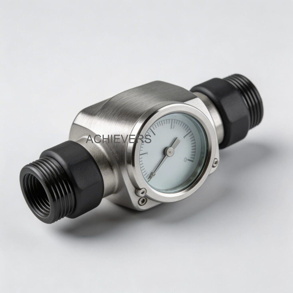
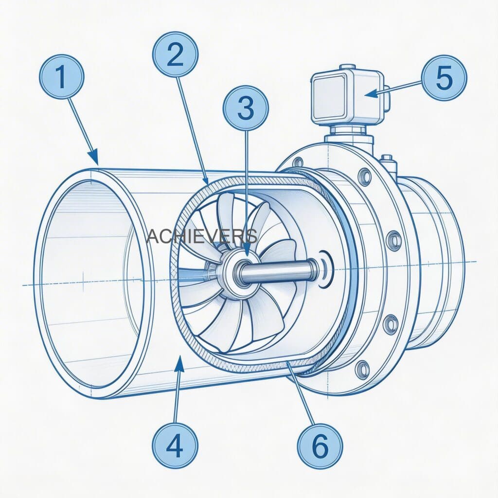
To troubleshoot effectively, you must understand the mechanics. An Oil Flow Meter utilizes an oval gear, positive displacement (PD) design. Inside the measuring chamber, two meshed oval gears rotate under the pressure of the flowing fluid. Each rotation sweeps a highly precise, discrete volume of liquid from the inlet to the outlet.
Because the volume per rotation is constant, the meter calculates flow by simply counting these rotations via magnetic sensors. This design relies on minimal clearance between the gears and the chamber wall. Therefore, it is exceptionally accurate (+/- 0.5%) for high-viscosity fluids but highly susceptible to solid particulates locking the gears or entrapped air artificially inflating the volume count.
2. Master Troubleshooting Matrix
When a fault occurs, cross-reference your exact symptom with this matrix before pulling the meter out of the piping block.
| Symptom | Likely Cause | Diagnosis Steps | Fix |
| — | — | — | — |
| Zero Flow Displayed (Fluid is moving) | Failed sensor or dead display battery | Check display power. Wave a magnet over the pickup to simulate gear rotation. | Replace battery, PCB, or magnetic pickup sensor. |
| Zero Flow Displayed (No fluid moving) | Seized oval gears due to particulates | Isolate meter, open chamber, inspect gears for debris or scoring. | Clean gears. Replace integrated mesh strainer. |
| Erratic / Jumping Readings | Entrapped air or gas pockets | Bleed system. Check suction side of the pump for air leaks. | Install an air eliminator upstream of the meter. |
| Accuracy Drift (Reading High) | Gear wear or fluid slip decreasing | Inspect gear clearances. Check for severe temperature/viscosity changes. | Recalibrate meter to current fluid viscosity via step-less calibration. |
| Accuracy Drift (Reading Low) | Partial blockage in the strainer | Monitor pressure drop across the meter. Open and inspect strainer. | Clean integrated mesh strainer and flush the line. |
| Display Error Codes | PCB fault or electrical noise | Check grounding. Measure supply voltage. Look for moisture in the register. | Re-seat wiring. Replace register cover gasket. |
| Leakage at Meter Body | Blown O-ring or loose bolts | Wipe clean, pressurize line, identify exact leak origin point. | Tighten flange bolts to spec or replace chamber O-rings. |
| Excessive Mechanical Noise | Cavitation or bearing wear | Listen for grinding (metal on metal) vs. popping (cavitation bubbles). | Lower flow rate to prevent cavitation. Replace bearings if worn. |
| Output Signal Loss (4-20mA) | Broken wiring or loop power failure | Use multimeter to verify loop voltage and check terminal connections. | Repair wiring. Replace signal transmitter board if burnt. |
| Valve Not Responding to Batch | Modbus communication failure | Check RS485 serial connections and verify PLC polling addresses. | Correct wiring polarity or reassign correct Modbus ID. |
3. Step-by-Step Field Diagnosis Procedure
When the matrix points to a mechanical or flow restriction issue, follow this standardized tear-down and diagnostic sequence. Do not bypass safety lockouts.
- Lock Out and Depressurize: Shut off the main pump. Close the upstream and downstream isolation valves. Relieve line pressure completely before loosening any bolts.
- Inspect the Strainer First: Remove the strainer cap. The Oil Flow Meter features an integrated mesh strainer. If this is clogged with pipe scale, sludge, or debris, clean it thoroughly with a compatible solvent.
- Check Free Rotation: Remove the electronic register top (it can be easily removed and rotated 90º). Use a non-magnetic tool to gently rotate the gears. They should turn smoothly with minimal resistance.
- Inspect for Mechanical Damage: If the gears bind, remove the front cover plate. Look for foreign objects, scoring on the chamber walls, or damaged gear teeth.
- Verify Clearances: Check the tolerance between the gears and the casing. Excessive wear here allows fluid to "slip" past without rotating the gears, causing under-registration.
- Eliminate Air: If the meter internals are flawless, the issue is likely process-related. Check the entire suction line for pinhole leaks where air can be drawn into the viscous oil.
- Test Electrical Continuity: For electronic control setups, isolate the signal wires. Use a multimeter to verify the 4-20mA loop is closed and generating the base 4mA signal at zero flow.
- Recalibrate via Step-Less System: If mechanicals and signals are healthy but accuracy is off, perform a step-less calibration using a known proving volume of the exact process fluid at operating temperature.
Pro Tip: Viscosity-Temperature Shift
Accuracy drift in positive displacement meters is rarely a sudden mechanical failure. It is almost always a temperature-induced viscosity shift. Heavy furnace oil heated to 150°C slips past gears differently than at 80°C. Always calibrate your meter at the exact operating temperature of the process fluid.
4. Installation Errors That Cause Ongoing Problems
Many troubleshooting calls stem from day-one installation mistakes rather than equipment failure. Correct these layout errors to permanently resolve recurring meter faults.
| Error | Symptom / Consequence | Correction |
| — | — | — |
| Removing the Strainer | Catastrophic gear lock-up | Never run PD meters without the integrated or upstream mesh strainer. |
| Improper Orientation | Rotor shafts wearing unevenly | Install so rotor shafts are completely horizontal, never vertical. |
| No Air Eliminator | Meter reads 10-20% higher than actual | Install an air eliminator on the discharge side of the pump, before the meter. |
| Pipe Strain | Meter body warping, causing internal binding | Support adjacent piping properly. Do not use the meter body to align pipes. |
| Shared Power Supplies | Erratic display or Modbus signal drops | Isolate the meter's power from high-draw equipment like a Fuel Dispenser. |
| Downstream Valve Placement | Flashing or cavitation inside the meter | Always install flow control valves downstream of the meter to maintain backpressure. |
5. Technical Specifications to Verify Limits
Ensure your application does not exceed the hardware's engineered limits. Operating outside these boundaries will cause rapid failure regardless of troubleshooting efforts.
| Specification | Value |
| — | — |
| Line Size Range | 006mm to 150mm (1/4" to 6") |
| Flow Rate Range | 1.0 LPH to 24,000 LPH |
| Accuracy | +/- 0.5% of reading |
| Repeatability | +/- 0.1% of reading (Better than 0.02% in optimal conditions) |
| Maximum Temperature | Up to 150°C (Suitable for high-temp Furnace Oil) |
| Construction Material | Lightweight aluminum alloys |
| Signal Outputs | Analog 4-20 mA and Serial RS485 MODBUS |
6. Preventive Maintenance to Avoid Recurrence
A reactive approach guarantees future downtime. Implement this maintenance schedule to ensure your Oil Flow Meter delivers its promised operational life.
- Weekly: Check the electronic digital display for low battery warnings. Do a visual sweep for flange leaks.
- Monthly: Pull and clean the integrated mesh strainer. Flush the basket with clean solvent.
- Quarterly: Verify the 4-20mA and MODBUS outputs against the PLC readings to ensure no signal degradation.
- Annually: Perform a volumetric proving test to check accuracy. Utilize the step-less calibration framework to adjust for normal annual wear. Inspect casing O-rings and replace if they show signs of compression set.
7. When to Call Service vs. Fix Yourself
Knowing when to stop dismantling and call the manufacturer prevents catastrophic damage.
Fix It Yourself If:
The display is dead (battery swap), the strainer is blocked (cleaning), the output signal wiring is loose (tighten terminals), or the meter needs a basic volumetric recalibration.
Call Factory Service If:
The oval gears are deeply scored, the rotor shafts are bent, the internal chamber shows metal shavings, or the primary PCB is scorched. Precision clearances cannot be machined in the field; attempting to file down gear teeth will permanently destroy the meter's +/- 0.5% accuracy.
FAQ
Q: Why does my meter register flow when the valves are closed?
A: This is usually caused by thermal expansion or line vibration. If the oil heats up in a locked pipe, it expands, pushing fluid slightly backward or forward. High-vibration environments can also trick the magnetic pickups. Ensure pipes are supported and check for thermal relief bypasses.
Q: Can I use this meter for both light vegetable oil and heavy furnace oil?
A: Yes, the aluminum alloy construction handles both. However, you cannot switch between vastly different viscosities without performing a recalibration. Calibrate the meter for the specific fluid currently in the line.
Q: How do I know if the integrated mesh strainer is blocked?
A: You will see a noticeable pressure drop across the meter, and the overall flow rate of your system will decrease. A best practice is installing pressure gauges immediately upstream and downstream of the meter to monitor this delta.
Q: Does an oval gear meter require straight pipe runs before and after?
A: No. Unlike turbine or ultrasonic meters, positive displacement meters are not affected by external factors caused by the installation layout. They do not require straight pipe conditioning runs.
Q: Why is my Modbus RS485 signal dropping out intermittently?
A: Signal dropouts are almost always caused by electromagnetic interference (EMI) or improper grounding. Ensure you are using shielded twisted-pair cables, ground the shield at one end only, and keep signal wires away from high-voltage AC lines.
Q: The gear chamber is stuck. Can I hit it with a mallet to free it?
A: Never strike the meter body or gears. You will warp the lightweight aluminum housing and destroy the micro-tolerances required for operation. Fully dismantle the chamber, soak in solvent, and remove the obstruction manually.
Q: How often do I need to recalibrate the meter?
A: For standard lube oils and process fluids, check calibration annually. For highly abrasive or extreme-temperature fluids (like 150°C furnace oil), prove the meter every six months to account for faster component wear.
If your system is still experiencing erratic readings after following this checklist, or if you need to upgrade to a meter correctly sized for your application, we can help. Contact our technical team today with your fluid type, maximum flow rate, and site operating temperature to get expert guidance on optimal flow measurement solutions.